What do Golf (the sport) and Car engines have in common?
Easy answer would be physics... duh... sure! But if you consider a simple design of the golf ball and the latest trend in engine head porting, things start to get more clear... and complex all at the same time.
Why? Well that is ways of the very tortuous world of : FLUID DYNAMICS (yes yes every mechanical engineer will have nightmares about flow calculations in Fluid Dynamics discipline and also thermodynamics applied to flow in fluid dynamics... I gather that bumps in suicide rates are probably related to these sort of calculations).
Fluid Dynamics!
And this is what we must understand in order to understand the concept of dimpling porting of engine heads. Why? Well because the concept divides mechanics and most of them are right as most of them are wrong!
Wooops? Right and Wrong all at once!
Most will defend you should port the head like this:
They are partially wrong!
Some will defend you should port the head like that:
They are also partially wrong!
But before we get into the details, let's look into the first counter arguments of Using or not Dimple porting:
Argument 1 - F1 cars don't use them
Sure but there are SEVERAL reasons for that.
1 - F1 engines run at VERY HIGH RPM, meaning that the CFM through the head is HUGE and the dimple designs work better for High and Low pressure areas. The F1 head channels have very little of those.
There is a simple theory to explain the engine CFM importance and that is the principle behind the not very well known Torque oriented VTEC system from Honda.
The Low rev Vtec system consisted in a capping of the 16valve head to run almost 12valve mode, so that the air going into the engine, at Low engine speeds, would have a higher velocity and uneven geometry while entering the cylinder
To produce Power numbers, you favor High speed, High turbulent, high flow instead of this non-turbulent flow. F1 engines are made for High Revs and as such High RPM. Not really for torque at low engine speed. This means that all optimization goes towards Direct, high speed flow... as we can see on point 2
2 - F1 engines have a HEAD design that is purposely made for high flow speed. While production cars consider space and compactness due to the valve train losses, the same principle does not exist in an F1 engine due to point nr 3.
F1 Cosworth v10 engine head port design
3 - F1 engines have Pneumatic Valve trains. F1 engines use a pneumatic valve train. This allows for a narrower angle on the valve train, and as such more direct port designs.
It also generated a valve lift time with a rather square wave, making the input of air FAR greater and and abrupt, making the acceleration and deceleration of air going in and out of the cylinder less progressive. Those are circumstances of a high rpm flow, and as such, the entire design considers flow and not particularly flow speed ant specific RPM's.... they are.. closer to forced induction than NA's in that manner.
Argument 2 - But then why aren't cars built like that?
Mythbusters had a saying about this. They tested a car, then the same car with clay added dimple panel features. Even considering the weight, of the clay the same car made a run with 27 and 29 mpg proving the dimple works of the airflow.
But if that is not enough for you, NASCAR rules banned dimpling the hoods, roofs, and trunks of their racing cars!
Argument 3 - My turbo engine didn't see any improvement... actually it makes less power.
Same principle as the F1 engine. The FORCED induction engine has ALL AIR under high pressure, so the regions of lower and higher pressure that an NA engine would suffer from are minimized by the forced induction nature of things. You don't really look towards minimizing pressure zones and looking for air velocity there! just size of ducts to make the air into the engine. The larger the better... simple math... dimples reduce this in 2 different ways as we are about to understand.
OK... so back to Fluid Dynamics.
An NA engine, particularly with a high efficiency intake plenum, or ITB's , needs to Accelerate the air into the cylinder, then decelerate as the valve closes, then re-accelerate, etc etc etc... and the acceleration will be crucial to allow the dynamics of the air flow to pull more air into the engine by using the flow inertia. So the speed that the air goes into the engine if very important, particularly on specific regions of the intake tubing (this very important part will be revisited later.)
Back to the golf ball
A clean surfaced ball will not go longer than the dimpled ball. will go slower than the dimpled ball and will be more prone to deviation by wind than the dimpled one.
Known fact for years that are easy to explain. The dimples "catch air" and create tiny swirls around the surface of the ball, as it goes through the air, the swirls become sort of a cushion of air. See how hovercrafts move? lookalike principle. Ever tried to move 2 glass sheets stacked together? Hard right?But if you add water or air between them, you can't make them stop!
Air is a fluid and as such it has a viscosity element to it. It sticks better to smooth surfaces and it slips better on fluids. So if you can make the layer slide to the surface swirl back and generate a cushion, the next layer of air slips through this cushion much faster than it would if in contact with the surface.
Not only that, but the drag that the swirl of the back side of the ball generates, also tends to break apart and not pull back on the ball as much, reducing the area exposed to back pull... Even cooler then!
Cool principle right? Right! So it must work with in any other situation... err no!
1 -First of all, the ball move through the air, not the air thought the ball so the principle is not exactly the same
2 -The ball is round and the main pressure point faces the wind... the inlet manifold tubing have bends and curves and features that can generate low or high pressures... it's not homogenized at all unlike the golf ball.
3 - The ball spins through the air. The engine inlet manifold doesn't.
4 - As you add dimples to a flow pipe, you are generating an invisible layer of air around the surface effectively REDUCING THE bore size! And the dimples alone, if surfaced clean, it would mean 1 to 2 more millimeters in bore size! AND THIS IS WHY ladies and gentlemen that:
- The turbo guy hates this because it produces less power
- The High speed engine hates this because it reduces intake tubing diameter.
HUM.. ok you're mean. You show me something cool and then it's is not applicable.
No... I'm not mean. Physics is thought... get a grip!
So so far we can conclude that dimpling can solve the drag problem.
That under pressured flow this is not really important, and that under NA flow this can be the result to more air speed and as inertia shows, quite more air into the engine.
We've also understood that the dimples will reduce physically and then in flow terms, the usable diameter.
So you are wrong! Dimples are bad and the smooth fellas are right.
Nooooo I told you physics is tough and fluid dynamics is even worse... so suck it up and let's continue our roller-coaster ride.
As usual, engineers base a lot of technology in studying, testing and resulting data.
The Intake ports have the following naming:
Different areas have different drag and high/low pressure zones:
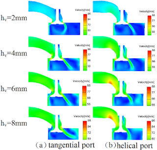
It also has different types of design, called Tangential port or Helical port.
Tangential ports are straight and very good for high speed flow. They product better high end power and are the preferred design for high performance engines.
Helical ports twist the air before the entrance of the cylinder, making the air enter the cylinder in a swirl movement.
Some cylinder designs used to have one Tangential port and a Helical one to generate a sort of compromise, sacrificing high end power over low end torque and usable mid range.
The Honda Low-rpm vtec explained earlier combined manages the best of both worlds, by allowing the low speed valve to open slightly, while the other opened fully, inducing and uneven air entry and resulting in a swirl, and then fully opening both valves at top end RPM with 2 Tangential ports providing the best flow.
Different port designs favor not only different engine applications, but also generate different low pressure zones.
Let's look at high pressure images of an intake side of an engine:
.jpg) Fair.. could do a little less on the shoulders and a bit of a strip of triangular shaped dimples right through that division
Fair.. could do a little less on the shoulders and a bit of a strip of triangular shaped dimples right through that division Hell no! Lose the shoulders dimples, add right down the end of the port where you have a smooth fully dragging surface before a squeeze!

.jpeg)


.jpeg)


No comments:
Post a Comment